Thanks very much for the reply, Fred! I've quoted the instructions I found below, they don't get repeated very often do they?!
While I was searching, I noticed some people complaining the thermocouple was "slow"... That seems to be the issue I'm having with mine. The thermostat works, it takes ages to react so the temperature swings much more than it should. The thermocouple wire on it looks like a thin coat hanger wire, not twisted like a 'K' type. Is that the problem?
About the PID controllers: I read that the heat sink and relay is necessary to avoid sparks, would this kit include the right stuff? (I've tried buying parts before and there's always some specification I get wrong through ignorance.)
http://www.ebay.co.uk/itm/4-IN-1-PID-KI ... 1c3e1280c9I couldn't mount it inside my bender so it would be a pretty large box of components. It would also cost more than the router controller and, sad as it is to say, money restricts my every decision. I've got a good thermometer, I'm tempted to buy a router controller and work out where to set the dial for the temps I want.
Frankly, I wish I could just buy something like the router controller. Learning about electronics isn't really on my list of things to do. I just need to know the simplest way of doing this. I just don't know about the voltage.
Alan wrote:
Mike,
The controller I used is the one on EBay that Fred mentioned (XMTD-718T). I'm sure that others would work, but you would need to verify the connections on the controller (120V, and relay contacts). This is being used in the on-off mode; when the temp exceeds the setting on the controller, the relay opens, removing power from the blanket. When the temp falls below the setting, the relay closes, connecting power to the blanket. Since the relay output is rated at 5A and the blanket is 8.5A, I added a 120V/10A secondary relay (Radio Shack part number 275-217). The timer was the timer that came with the bender that I got from John Hall.
Here is what I did:
First, I drilled a 3/4" hole in the side of the bender and screwed in a cable clamp for the power cord. It was a nice tight fit, so no need to use the nut on the cable clamp (see "cable clamp" picture attached).
I then removed the small piece of birch ply on the front of the bender and replaced it with a larger piece to mount the controller, timer, and outlet (see attached "front" picture).
Wiring:
The thermocouple connects to terminal 1 and 2 on the controller (Blue lead on terminal 1, red lead on terminal 2).
The black (hot) lead from the 120v power cord connects to controller terminal 12.
The white (neutral) lead from the 120V power cord connects to controller terminal 11.
A jumper between the controller terminal 12 and terminal 9.
Connect controller terminal 8 to pin 8 on the Radio Shack relay.
Connect pin 7 on the Radio Shack relay to terminal 11 on the controller.
Connect pin 5 on the Radio Shack relay to terminal 9 on the controller.
Connect pin 3 on the Radio Shack relay to the input of the timer.
Connect the output of the timer to the gold (hot) terminal on the outlet.
Connect Pin 11 on the controller to the silver (neutral) terminal on the outlet.
I also attached a drawing of the wiring diagram.
Again, thanks to Fred for the link and helping me to get it hooked up.
Hope this helps.
Alan
Dave Fifield wrote:
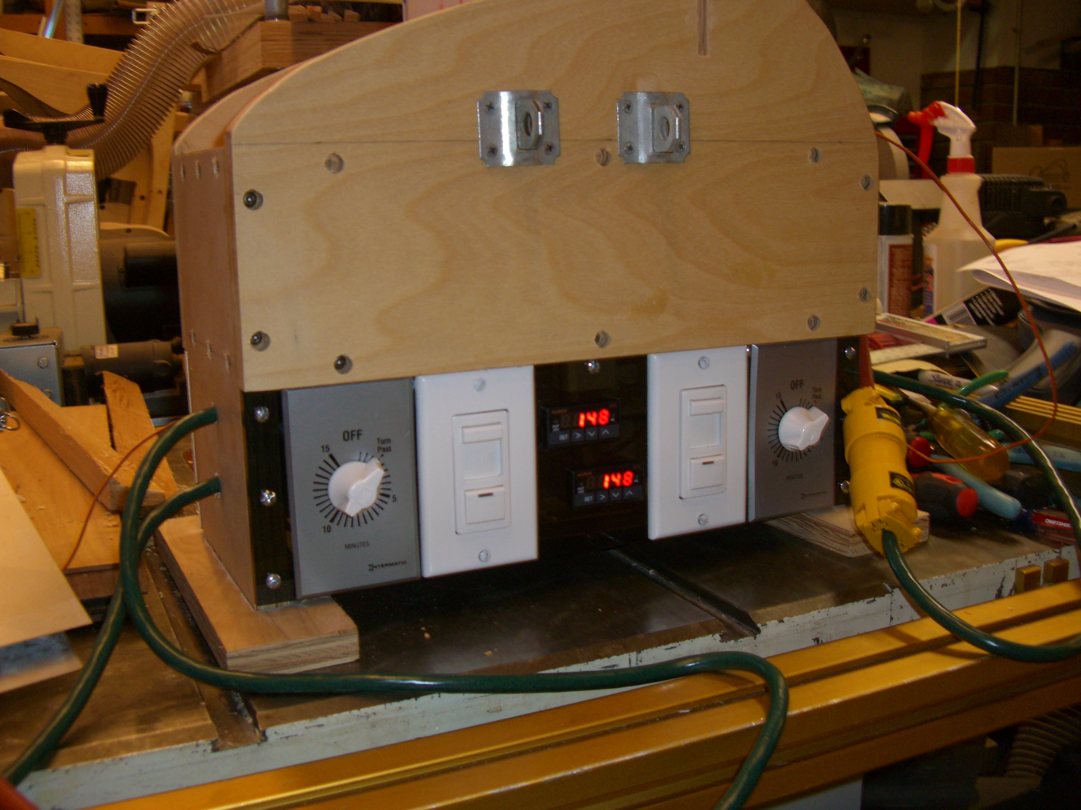
I want to thank all of you for the information posted in this thread. Most helpful!! It got me fired up to convert my Fox Style Bending Machine over to a temperature controlled rig. I found some different PID controllers on eBay (bit cheaper than the ones cited above). I made two channels, one for each blanket - either two big blankets in a sandwich or (what I have right now) a big blanket and a smaller extra blanket for doing cutaway bends. I cut the front panel out of some smokey acrylic sheet using my laser - didn't have to drill a single hole!

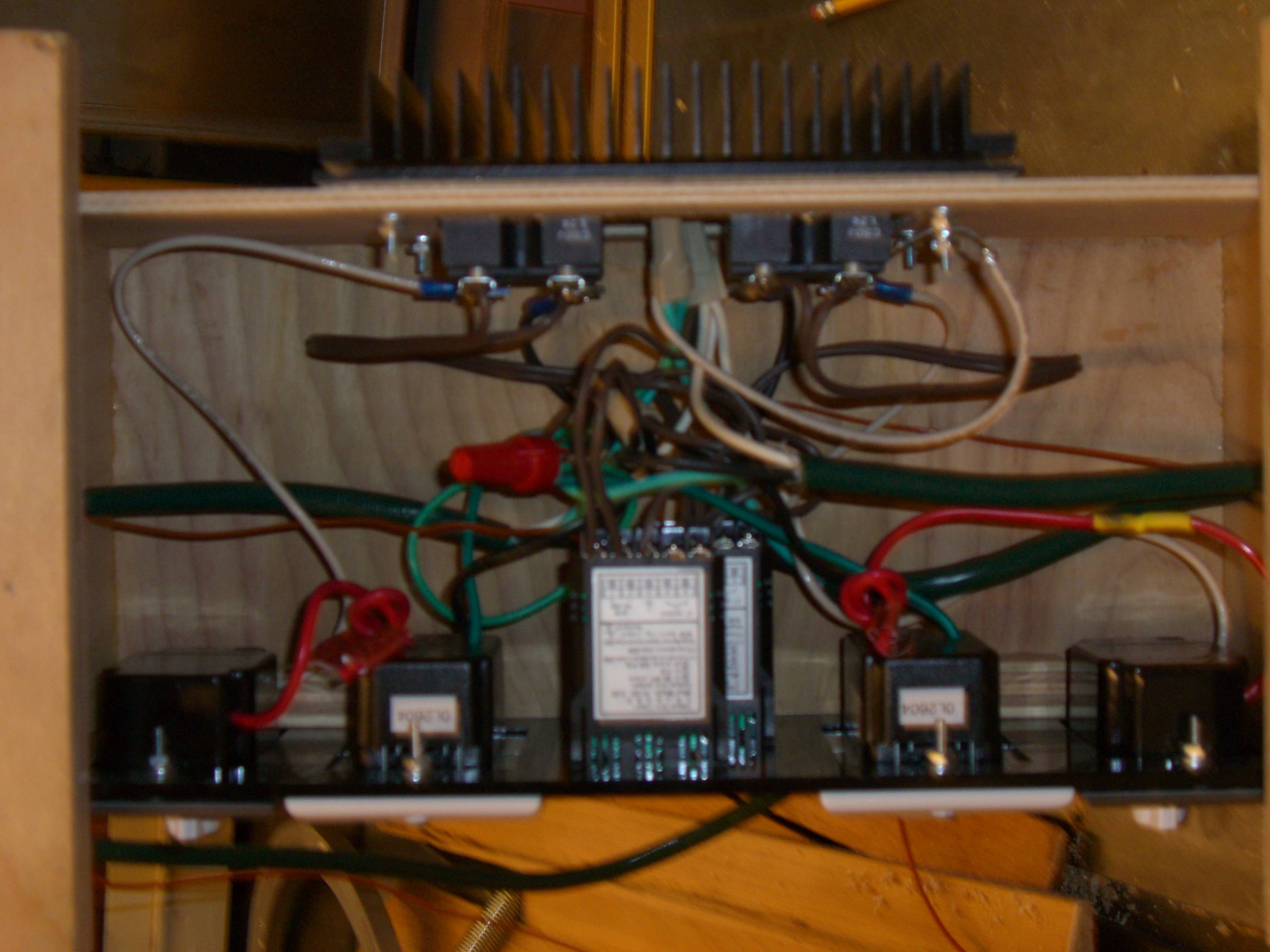
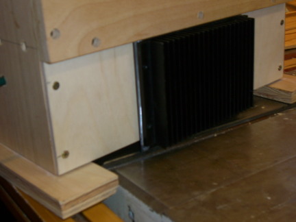
I put a couple of 15 minute clockwork timers and some 1KW dimmers in series with the blankets, but I found (after I had it up and running, of course!) that the dimmers really aren't needed at all. Also, I put the two solid-state relays on a substantial heatsink (from a local electronics surplus store) on the back panel, but found the heatsink really isn't necessary either! A simple sheet of aluminum for the back panel would have sufficed.
I didn't use the K-type thermocouples that came with the PID controllers - they were too chunky for my liking. I splashed out on a couple of Fluke thermocouples (they sell them as spares for their multimeters). These are much thinner/sleeker probes, and covered with Teflon.
Here's a few pictures of my converted rig. Right click on them to see/download the high resolution version:


I put a plywood bottom on the unit after taking these photos, so it's safe from prying fingers. The auto-tune function on these PID controllers works beautifully. Like Nelson said above, it's interesting to watch them do their stuff! All in all I'm very pleased with this modification. Thanks again to all of you for pointing me in the right direction.
Oh, so now my old LMII manual controller is not going to be used ever again (by me). Anyone interested in it? I'll let it go cheap. PM me if you're interested.
Cheers,
Dave F.