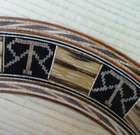
Official Luthiers Forum!

Owned and operated by Lance Kragenbrink
It is currently Sat Jun 15, 2024 5:06 pm


All times are UTC - 5 hours


Post new topic Reply to topic  [ 19 posts ] 
Author Message
 Post subject:
PostPosted: Wed Sep 19, 2007 2:18 pm 
Offline
Cocobolo
Cocobolo
User avatar

Joined: Thu Aug 03, 2006 4:48 pm
Posts: 204
Location: Wayne, NJ, United States
First name: Gary
Last Name: Lee
Status: Professional
General Description
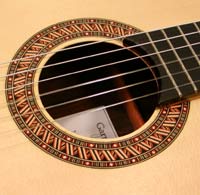
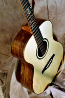
The following describes a method to construct an elevated fingerboard on a classical guitar. The result is an upper bout in the style of Byers and others, where the neck/fingerboard assembly sits above a soundboard that dips below the plane of the lower bout (Fig. 1). I have not seen how other builders execute their elevated fingerboards, but the method I developed works well and overcomes several technical hurdles in obtaining correct neck angle and head placement.

Fig. 1. Finished guitar.


The angle in the neck extension that creates the elevation over the upper bout continues past the body where it meets the heel block. Therefore, the top of the heel block has an angle that is complementary with that of the neck extension.

The neck/body joint uses a spline. The original intent was to glue the spline joint, but midway through construction, it became obvious that there are overwhelming advantages in converting from a glued spline joint to essentially a bolt-on, double mortise and tenon joint, as seen on many steel string instruments (Fig. 2). The advantages lie mainly in the ability to consistently place and hold parts during fitting. There is no reason, however, why a glued joint cannot be used with this method, but I have not detected any sonic or structural weaknesses in the bolting method.

Fig. 2. Unassembled body and neck.


Preparing the Soundboard
The soundboard is braced normally using a dished solera and go-bar deck, except that a ramp that matches the desired elevation profile (minus fingerboard) is attached to the upper bout of the solera (Fig. 3). With the ramp attachment, the soundboard will retain the shape of the fall-away once braced. The ramp attachment is made by gluing together many smaller ramps that are reproduced by template routing. In this case, the profile of the elevation is designed to have 3 mm of neck (not including fingerboard) protruding above the soundboard at the soundhole and 11 mm at the 12th fret (front of body). The fall-away of the soundboard from the plane of the lower bout begins gradually at the edge of the soundhole (bridge-side) and then extends in a straight line to the front-end of the body. There is no side-to-side doming in the upper bout.

Fig. 3. Solera with ramp attachment.


Mortised Head Block
The head block is “U”-shaped, with a long, upper portion to support the neck extension (Fig. 4). Before being shaped, the block begins as a solid mahogany blank with a 10 mm wide mortise cut with a table saw and dado blade. The sides and head block are profiled to match that of the solera’s ramp attachment. Fig. 2 shows a front view of the mortise with the body fully assembled.

Fig. 4. View of head block and profiled sides before gluing the top.


Preparing the Neck Extension
The most problematic step in constructing an elevated fingerboard is cutting the proper angle in the neck extension and establishing a good fit between the bottom of the extension and the soundboard. It is generally agreed that proper classical neck angle can be achieved when the plane defined by the top of the frets extends to approximately the middle of the front of the bridge (height-wise). For a standard classical bridge of 8 mm in height, this would be 4-5 mm above the soundboard. 5 mm is used here. Given that the fingerboard used in this case is 6.5 mm thick, the frets 1 mm tall, and the desired neck extension thickness above the soundboard (at the soundhole) is 3 mm, the top plane of the frets would sit 6.5 + 1 + 3 = 10.5 mm above the soundboard at the top of the soundhole. To model the desired neck angle, blocks with these heights are placed at the soundhole and bridge positions, and a straight edge (in this case a carbon fiber rod) is rested on the blocks (Fig. 5). In this case the distance from the top of the soundboard at the 12th fret to the bottom of the rod is measured to be 18.5 mm. This means that the height of the neck extension at the 12th will be 18.5 - 6.5 - 1 = 11 mm. The geometry of these dimensions gives an angle of about 4 degrees.

Fig. 5. Method to model the angle of the neck.


To create the angle in the neck extension, the neck is fixed to a jig with a sandpaper-covered (for grip), adjustable ramp, and then cut with a router riding on the fixed rails of the jig (Fig. 6). The jig’s ramp is attached with a hinge at one end (Fig. 7), and can be adjusted to any desired angle at the other end via a bolt that is screwed into a threaded insert (Fig. 8). The desired angle can be set by adjusting the height of the bolt according to the formula: height = length of ramp from hinge to bolt x tan(desired angle). Reality check: before cutting the real neck blank, cut a scrap piece of wood from a 2x4 that models the full height of the neck blank + fingerboard + frets. Test fit the model over the upper bout—the top plane should line up with the 5 mm block at the bridge position. If necessary, slightly adjust the ramp’s angle, repeat on the scrap model until the fit is perfect. There is a small amount of latitude here for moving the neck forward or backward to achieve the proper alignment.

Figs. 6-8. Cutting the angle in the neck with the adjustable-angle jig.


Final Fitting of the Neck Extension
There will be a small amount of arching in the upper bout, particularly near the soundhole where the fall-away begins. The underside of the neck extension can be fine-tuned with a scraper to exactly match the surface of the soundboard.

Fixing the Position of the Neck
When the final fit is perfect, the neck is positioned and clamped to the body through the soundhole. To bolt the neck in place, two holes are drilled through the neck, soundboard, and head block extension to accept a pair of ?-20 x 1” (3/16” hex head) bolts stabilized by washers and lock washers (Fig. 2). The holes in the neck extension are widened and countersunk to accept threaded prong nuts that receive the bolts. The neck can now be bolted to the body by reaching through the soundhole (Fig. 9). With the neck in place, the top of the heel block (pre-cut with a 10 mm-wide mortise) is given the complementary angle of the neck extension angle using a belt sander. The test fit between the heel, neck, and body should be made with a spline in place to reference the body to the heel block. When the fit is perfect, the rough shape of the heel block is cut on a bandsaw (Fig. 10), the neck is removed from the body, and the majority of the heel block cheek material is removed by undercutting with a chisel. The final fit of the block’s cheeks is achieved by taping sandpaper to the body on both sides of the mortise, inserting a spline into the mortise to index the heel block, and running the block back and forth until fully seated.

Fig. 9. Neck bolted to body and heel block shaped with complementary angle. Note the carbon fiber rod inserted into the neck for added stiffness.


Fig. 10. Heel block blank with complementary angle (left) and rough-shaped heel (right).


Installing the Heel Bolt
With the neck and heel properly fitted, maple inserts and splines are epoxied into position as shown in Fig. 2. The inserts fill the middle of both heel and head blocks where the bolt hardware will be placed, while splines are glued into the top and bottom of the heel block and will extend into the body’s mortise. A hole is next drilled through the head block insert and head block to accept a furniture bolt, and another hole is drilled through the heel block insert and partially through the heel itself to accept a threaded insert. Both the neck and heel can now be bolted to the body and tested for fit.

At this point, the neck and heel are not glued together. Instead, the head is prepared next and fitted to the neck shaft using a V-graft. The reason for this sequence is that prior to fixing the position of the neck to the body using the bolts, there is some uncertainty as to where exactly the head must attach to the neck. For this reason, a V-joint is chosen over a scarf joint because the V-graft can be placed very precisely and the entire head can be prepared independently of the neck and attached at a later time.

Preparing the Neck V-Graft Tenon
With the neck bolted into place, the position of the neck/head junction is marked and the tenon of the V-joint is first rough-cut on a band saw, placed on a jig with an 11 degree ramp fitted with a tenon-shaped template, and then cut with a router fitted with a 1/4” diameter spiral flush trim bit (Whiteside) (Fig. 11). The jig has tracks parallel to its base, an acrylic template for the tenon that is bolted to the base, and holes in the rails through which the neck can be clamped to the sandpaper-covered ramp (Fig. 12). After routing the tenon, the inside corners left round by the router bit are finished with a chisel. Note: For a 45 mm long tenon and 18 mm thick head joined at 11 degrees, the neck blank must start at least 28 mm thick. If the cutting length of the flush trim bit is not long enough to cut through the entire depth of the neck blank, the top and bottom of the tenon must be first reduced in thickness--the top reduced by routing in the jig with the tenon side at the top of the jig’s ramp, and the bottom reduced by routing in the jig with the neck turned around and the tenon placed at the bottom of the ramp.

Fig. 11. Routing the neck V-graft tenon in the ramped jig.


Fig. 12. Finished V-graft tenon.


Fig. 13. Ramped jig for cutting neck tenon.


Preparing the Head V-Graft Mortise
The head material is reduced to approximately 18 mm thick, rough cut on a bandsaw, bolted horizontally on a jig with router rails, and then shaped with a flush trim bit that follows a complementary mortise template (Fig. 14). After routing the mortise, the inside corners left round by the router bit are finished with a chisel.

Fig. 14. Routing the head V-graft mortise.


Head Profile and Roller Slot Shaping
After the head plate is glued, the head profile is routed, roller holes are drilled, and then the roller slots are routed (Figs. 15 and 16).

Fig. 15. Template routing the head profile. The head is secured with bolts positioned in the eventual roller slots.


Fig. 16. Jig for template routing the roller slots. The head is secured through the roller holes.


Gluing the V-Graft.
The joint is glued with hot hide glue using horizontal and vertical pressure (Figs. 17-18).

Fig. 17. Gluing the V-graft.


Fig. 18. Completed V-graft.


Final Assembly of the Neck, Heel, and Body
With the head attached, the neck/heel assembly is dry-fitted to the body by firmly bolting the neck to the body, and bolting the heel to the body snuggly but not fully tightened. The heel is clamped to the neck and two ?” holes are drilled vertically through the two pieces to accept dowels. The parts are unbolted and the body’s surfaces are covered with waxed paper to protect it from glue. With glue applied, the process is repeated, dowels are inserted, and the assembly is clamped (Fig. 19). Gluing the assembly in situ assures that the neck will fit to the body perfectly when dry. After the neck is assembled, the fingerboard is installed, and the neck is shaped and finished.

Fig.19. Final neck assembly. Note dowels beneath the blue clamp.


Top
 Profile  
 
 Post subject:
PostPosted: Wed Sep 19, 2007 2:32 pm 
Offline
Contributing Member
Contributing Member
User avatar

Joined: Mon Mar 19, 2007 7:05 am
Posts: 9191
Location: United States
First name: Waddy
Last Name: Thomson
City: Charlotte
State: NC
Focus: Build
Status: Semi-pro
Nice tutorial, Gary.   Great details.    

_________________
Waddy

Photobucket Build Album Library

Sound Clips of most of my guitars


Top
 Profile  
 
 Post subject:
PostPosted: Wed Sep 19, 2007 2:34 pm 
Offline
Mahogany
Mahogany

Joined: Sat Mar 10, 2007 1:36 pm
Posts: 69
Location: lockport ,il
great tutorial Gary. that is some awesome work there.


Top
 Profile  
 
 Post subject:
PostPosted: Wed Sep 19, 2007 2:57 pm 
Offline
Brazilian Rosewood
Brazilian Rosewood
User avatar

Joined: Thu Mar 01, 2007 3:15 pm
Posts: 2302
Location: Florida

I'm still not sure why you did this, but the effect is awesome! I'm afraid it would take me a little time to get used to playing with a neck that isnt in the same plane as the guitar top.


GREAT tutorial !


_________________
Reguards,

Ken H


Top
 Profile  
 
 Post subject:
PostPosted: Wed Sep 19, 2007 6:04 pm 
Offline
Brazilian Rosewood
Brazilian Rosewood
User avatar

Joined: Tue Jul 05, 2005 10:53 pm
Posts: 2198
Location: Hughenden Valley, England
Gary,

That's great engineering and craftsmanship. A really useful and comprehensive tutorial. Thanks.

You are only a few steps away from doing a fully adjustable classical guitar neck.

_________________
Dave White
De Faoite Stringed Instruments
". . . the one thing a machine just can't do is give you character and personalities and sometimes that comes with flaws, but it always comes with humanity" Monty Don talking about hand weaving, "Mastercrafts", Weaving, BBC March 2010


Top
 Profile  
 
 Post subject:
PostPosted: Wed Sep 19, 2007 6:15 pm 
Offline
Cocobolo
Cocobolo
User avatar

Joined: Fri Dec 01, 2006 6:44 pm
Posts: 471
Location: Australia
First name: Allen
Last Name: McFarlen
City: Mt. Sheridan
State: Qld.
Zip/Postal Code: 4868
Country: Australia
Focus: Build
Status: Professional
That was a great turtorial. I'm built a raised fret board on my latest guitar, an OM, but my method is no were near as well executed as yours. Great inspiration for my next attempt.

_________________
Allen R. McFarlen
Barron River Guitars & Ukuleles
Facebook
Cairns, Australia


Top
 Profile  
 
 Post subject:
PostPosted: Wed Sep 19, 2007 9:30 pm 
Offline
Koa
Koa
User avatar

Joined: Mon Sep 11, 2006 3:56 am
Posts: 855
Location: United States
Gary,

Great, great tutorial! I stand in awe of your work on this one. I have thought about developing a bolt-on neck for my guitars in the future. You have provided some great ideas and a level of precision to shoot for.

BTW, thanks so much for your help in the past too.

Best regards,
Max

_________________
Max Bishop
Brighton, Michigan


Top
 Profile  
 
 Post subject:
PostPosted: Wed Sep 19, 2007 10:32 pm 
Offline
Koa
Koa
User avatar

Joined: Wed Dec 07, 2005 9:08 am
Posts: 534
First name: Pete
Last Name: Liccardello
City: Eden Prairie
State: Minnesota
Gary,

Many thanks for taking the time to publish this tutorial. It takes the mystery out of the elevated neck construction and I'm looking forward to trying it myself in an upcoming build.

The Assad bros. and Sharon Isbin playing the Humphrey design always are a good listening experience. Here is a link to one of my favorites:

    Assad Bros. - Tango Suite

I owned a Martin/Humphrey CTSH for about 4 years and finally sold it late last year. I was always pleased with the harp-like tone it had which I attributed to the neck angle really driving the bridge and it's lattice bracing. It was really a joy to play Bach and baroque music on it.

I'd be interested to hear your take on the tone qualities of your instrument.

Regards,

Peter

_________________
Peter


Top
 Profile  
 
 Post subject:
PostPosted: Wed Sep 19, 2007 10:36 pm 
Offline
Koa
Koa

Joined: Wed Jun 01, 2005 6:35 am
Posts: 1325
Location: Kings Mtn., NC, USA
First name: Bill
Last Name: Greene
City: Kings Mountain
State: North Carolina
Zip/Postal Code: 28086
Country: USA
Focus: Build
Status: Amateur
Ditto what several others have said. I don't build classicals, but this tutorial was as thorough, articulate and well laid out as any I've seen. This should definitely be in a tutorial file somewhere for reference.

That took a lot of time. Impressive work indeed. =D>]

_________________
Eagles may soar, but weasels don't get sucked into jet engines.


Top
 Profile  
 
 Post subject:
PostPosted: Wed Sep 19, 2007 10:56 pm 
Offline
Brazilian Rosewood
Brazilian Rosewood

Joined: Tue Nov 29, 2005 11:44 am
Posts: 2186
Location: Newark, DE
First name: Jim
Last Name: Kirby
Focus: Build
Status: Amateur
Gary - Thanks very much for that. Very illuminating!

A few technical questions. I was wondering if the change in the soundboard geometry also leads to any change in the angle of the neck relative to the original plane of the top, in comparison to what you would have used without the fall-away of the top. Is the relation between the neck position, bridge and plane of the lower bout unaltered? Is the doming in your solera for the lower bout the same as it would be for a regular flat top?

Thanks again,

Jim


_________________
Jim Kirby
kirby@udel.edu


Top
 Profile  
 
 Post subject:
PostPosted: Wed Sep 19, 2007 11:11 pm 
Offline
Koa
Koa
User avatar

Joined: Tue Nov 28, 2006 1:44 pm
Posts: 1105
Location: Crownsville, MD
First name: Trevor
Last Name: Lewis
City: Crownsville
State: MD
Zip/Postal Code: 21032
Country: USA
Focus: Build
Status: Semi-pro
Cool idea...I have some neck blocks at home that look exactly like those. Just when you think you have a new idea....!   

Here's a few points on how I'm using this part:

I'm making a steel string acoustic with a fully carved back (all done on my CNC). I leave a flat area up front and in the back as neck/tail block glue up surfaces. I cut the top of the neck block so that it has a 2 degree tangency to the front of the neck block....this neck block top curve then runs along a 28' radius to the back of the block.

I also CNC cut/profile my sides before bending...they are pre-cut so that when I bend them to the profile I've chosen, I should have a pretty clean wedge right at the start. These mate right up to the head block and tail block heights..

As for the neck/body joint...I've got some tricks worked out there to relieve the back of the heel 2 degrees to get the right neck angle.

I'm shooting to get a more precise and quicker build. I built one acoustic with the carved back and I love the tone but the neck angle wasn't the best...so I've been playing with all this design stuff recently to make this next one better. Sorry to ramble on...I just got excited when I saw that neck block!


_________________
http://www.PeakeGuitars.com


Top
 Profile  
 
 Post subject:
PostPosted: Thu Sep 20, 2007 3:45 am 
Offline
Brazilian Rosewood
Brazilian Rosewood

Joined: Fri Nov 03, 2006 6:50 pm
Posts: 2711
Location: Victoria, BC
First name: John
Last Name: Abercrombie
Status: Amateur
Thanks, Gary.
An elevated fingerboard classical is on 'the list' for me to do later this year, and I know I'll be referring to your tutorial a lot when the time comes.
I appreciate the time you took to do this.
Cheers
John


Top
 Profile  
 
 Post subject:
PostPosted: Sat Sep 22, 2007 1:17 am 
Offline
Cocobolo
Cocobolo
User avatar

Joined: Thu Aug 03, 2006 4:48 pm
Posts: 204
Location: Wayne, NJ, United States
First name: Gary
Last Name: Lee
Status: Professional
Ken,
Elevated fingerboards are the "classical guitarist's cutaway". Even a slight elevation makes access to the upper positions much easier. Despite the unique look, it's amazing how quickly one gets used the feature. To the conservative classical crowd, it's much more appealing and acceptable than a cutaway.

With the presence of the neck extension, the design just begs to be attached like a double mortise and tenon. And like Dave correctly points out, a fully adjustable neck is the natural extension to the design.


Top
 Profile  
 
 Post subject:
PostPosted: Sat Sep 22, 2007 1:24 am 
Offline
Cocobolo
Cocobolo
User avatar

Joined: Thu Aug 03, 2006 4:48 pm
Posts: 204
Location: Wayne, NJ, United States
First name: Gary
Last Name: Lee
Status: Professional
Peter,
   Thanks for the enjoyable link. I too like the sound of the Assads' Milleniums, and of course, their stellar playing. I'm also very fond of Adam Holzman's Millenium. What a killer sound!

I discussed a little bit about the sound of my guitars here


Top
 Profile  
 
 Post subject:
PostPosted: Sat Sep 22, 2007 2:00 am 
Offline
Cocobolo
Cocobolo
User avatar

Joined: Thu Aug 03, 2006 4:48 pm
Posts: 204
Location: Wayne, NJ, United States
First name: Gary
Last Name: Lee
Status: Professional
Jim,
In this case, I used the same solera that I use for traditional classicals. The board is scooped to 2.5 mm deep in the lower bout with the maximum just in front of the bridge. The depression gradually extends in a teardrop shape to the soundhole. The fall-away in the upper bout smoothly continues this lower bout arch.

The fingerboard, nut, and saddle positions in these guitars remain essentially unaltered relative to that of my traditional guitars. The sound of the two guitars built with the elevation is slightly smoother and less edgy than the traditional, and the left and right hand feel a little softer. These results are perhaps a consequence of the extension of the arch from the lower bout into the upper.

With the method I presented to measure and cut the neck, there is no reason why one cannot build any fall-way desired. In fact, it's probably not worthwhile to think in terms of fall-away anyway (which is a lower bout-centric concept) since it's all about the relative positions of the nut, frets, and saddle in space. Humphrey's Millenium design, where the whole body is in the shape of a wedge (to deliver more string energy to the soundboard), certainly embraces this idea.


Top
 Profile  
 
 Post subject:
PostPosted: Sat Sep 22, 2007 2:03 am 
Offline
Cocobolo
Cocobolo
User avatar

Joined: Thu Aug 03, 2006 4:48 pm
Posts: 204
Location: Wayne, NJ, United States
First name: Gary
Last Name: Lee
Status: Professional
Parser,
I would love to see some pictures if you have them!


Top
 Profile  
 
 Post subject:
PostPosted: Sat Sep 22, 2007 8:26 am 
Offline
Contributing Member
Contributing Member
User avatar

Joined: Thu May 12, 2005 5:46 am
Posts: 2945
Location: United States
Gary,
Thank you for excellent tutorial. I've been thinking of doing an elevated fingerboard and a drop off on the top similar to that.
I'm not sure if you've seen it or not but I think Greg Byers has an article in an old GAL pub. on the drop off top. You may be familar with it.
Excellent job!

_________________
Jim Watts
http://jameswattsguitars.com


Top
 Profile  
 
 Post subject:
PostPosted: Sat Sep 22, 2007 9:58 am 
Offline
Brazilian Rosewood
Brazilian Rosewood

Joined: Tue Nov 29, 2005 11:44 am
Posts: 2186
Location: Newark, DE
First name: Jim
Last Name: Kirby
Focus: Build
Status: Amateur
Gary - Thanks for the discussion of bridge and fretboard geometry.

Your guitars' aesthetics just knock me out. I wish I could hear one - I should make a trip up to NJ someday. (Sorry I didn't make it when you were only a little over an hour away).

Jim


_________________
Jim Kirby
kirby@udel.edu


Top
 Profile  
 
Display posts from previous:  Sort by  
Post new topic Reply to topic  [ 19 posts ] 

All times are UTC - 5 hours


Who is online

Users browsing this forum: No registered users and 6 guests


You cannot post new topics in this forum
You cannot reply to topics in this forum
You cannot edit your posts in this forum
You cannot delete your posts in this forum
You cannot post attachments in this forum

Jump to:  
cron
Powered by phpBB® Forum Software © phpBB Group
phpBB customization services by 2by2host.com